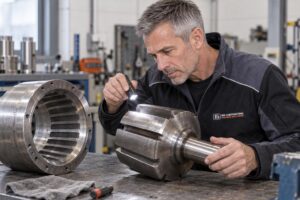
Recognising rotor and stator wear begins with a combination of process deviations, changes in noise or vibration behaviour and a visual inspection of the rotor-stator gap and working surfaces. Lower dispersing performance, a longer process time, metal particles, grooves, rounded edges or localised contact are clear indications, but one signal on its own does not prove that the rotor-stator pair is worn. The key question is therefore not only whether wear is present, but also which mechanism is causing it; without this diagnosis, a new component may also suffer premature damage.
Rotor-stator wear is material loss or permanent geometric change to the rotating rotor and stationary stator, which changes the gap, flow and shearing action of a dispersing machine.
Do not wait until the machine is barely dispersing at all. Progressive wear can lead to a broader particle size distribution, reprocessing, product contamination and unplanned downtime. If you notice a sudden change in vibration, hear scraping contact or find metal particles, the machine must be stopped and inspected in accordance with the applicable safety procedure.
Recognising rotor and stator wear from six signs
The most reliable diagnosis is obtained when several signals point in the same direction at the same time. Process performance, mechanical behaviour and visual condition must therefore be assessed together and compared with a known baseline.
| Sign | What you observe | Possible explanation | Required check |
|---|---|---|---|
| Lower dispersing performance | The desired product result requires more passes or longer recirculation | A larger effective gap or rounded working edges reduce the local shear stress | Compare the recipe, temperature, viscosity, residence time and rotor-stator geometry |
| Broader or variable product result | Particle distribution, homogeneity or emulsion quality varies between batches | Uneven wear changes the flow through the openings | Check both the product data and the full circumferential view of the rotor and stator |
| Different noise or vibration pattern | The machine sounds rougher, pulsates or exhibits new vibrations | Imbalance, bearing problems, misalignment, foreign material or rotor-stator contact | Stop safely and inspect the drive, bearings, mounting and process head |
| Visible material loss | Edges are rounded, surfaces are polished or openings are deformed | Abrasion, erosion, cavitation or chemical attack | Compare with reference photographs and the manufacturer’s permitted dimensions |
| Grooves or localised damage | Scratches, burrs, gouges or one-sided contact marks are visible | Foreign objects, eccentric running, an assembly error or deformation | Investigate the cause before restarting or replacing |
| Particles in the product or rinsing liquid | Unexplained metallic fragments appear during inspection | Active material loss from the process head, pipework or other components | Isolate the source and assess product safety with QA or QC |
Process performance usually deteriorates gradually
A worn rotor-stator combination builds up pressure and velocity gradients less effectively in the working zone. When sharp working edges become rounded or the gap increases, the local shear stress decreases and agglomerates are subjected to less intensive loading. As a result, the product may need to recirculate for longer before the same fineness, homogeneity or emulsion quality is achieved.
Do you know whether the current longer process time is genuinely caused by the process head, or have the viscosity, powder feed, temperature or recipe sequence changed at the same time? This question is essential because increasing viscosity affects the volumetric flow rate and residence time and can therefore cause the same symptom. The function of the geometry is discussed in more detail under rotor-stator geometry and particle size reduction.
Noise and vibrations reveal sudden damage
A new tone, pulsating noise or abrupt vibration is not normal evidence of uniform wear, but a reason to investigate a mechanical problem immediately. Rotor-stator contact, a loose component, bearing damage, imbalance or a hard foreign object can cause far greater damage in a short time than gradual abrasion.
Never assess noise by listening close to a rotating process head or by removing guards. Use available trend data and follow the installation’s safety and lockout procedure. Allowing a machine to continue running to see whether the noise disappears by itself can turn repairable damage into failure of the process head, shaft or bearings.
The wear pattern shows where the load originates
Uniformly polished working surfaces are more consistent with erosive or abrasive loading, while a one-sided contact mark indicates a geometric or mechanical problem. Deep grooves and broken edges are more commonly associated with hard foreign objects. Pitting, discolouration and a spongy surface, by contrast, may resemble chemical attack or cavitation.
A shiny surface does not automatically require rejection. Some products polish the material without immediately taking the functional geometry outside tolerance. Conversely, a rotor may look visually sound even though rounded edges and a changed gap are already impairing dispersing performance.
The shape of the mark is therefore often more informative than the amount of shine. Photographs of a new or previously approved process head, taken from fixed positions, make small changes much easier to recognise than inspection from memory.
“In practice, we see that operators often compensate for performance loss by increasing the rotational speed. You temporarily mask the wear by doing so, but accelerate the eventual damage.”
Bart Brouwer
Sales Manager
For a remote assessment, product data and photographs alone are not always sufficient. The permitted gap, material selection and rejection criteria differ by version, while the actual load depends on viscosity, density, particle hardness, concentration, temperature and operating mode.
Four wear mechanisms each require a different measure
Wear on a rotor and stator is not a separate fault, but the result of abrasion, contact, cavitation or corrosion. Replacing components restores the geometry, but only prevents recurrence if the dominant mechanism is also eliminated.
Abrasion and erosion caused by the product flow
Abrasive wear occurs when hard particles move along the working surfaces and cut away or polish off material. Erosion is caused by repeated impact from product and particles, particularly in areas where the flow accelerates or changes direction sharply. A higher solids loading, poorly wetted agglomerates and hard contaminants can increase this load.
The most common assumption is that a higher tip speed exclusively produces a better dispersing result. A higher relative speed generally also increases the mechanical load on the rotor, stator and product particles. More shear is therefore not necessarily better; the required energy input must be appropriate for the material and the desired endpoint.
Mechanical contact caused by alignment, bearings or assembly
During normal operation, the rotor and stator should not run against each other in an uncontrolled manner. One-sided scratches, annular contact marks, burrs and local heat discolouration may indicate eccentricity, shaft deflection, damaged bearings, deformed components or incorrect assembly.
Is the wear clearly more severe on one side than on the opposite side? If so, uniform product abrasion is unlikely, and runout, mounting, bearings and assembly must be investigated first. Replacing only the damaged rotor-stator pair is not the correct solution in that situation because the mechanical cause remains present.
Cavitation and insufficient product supply
Cavitation can occur when vapour or gas bubbles form locally and then implode in a high-pressure area. The repeated local load can cause pitting and is sometimes accompanied by a crackling or gravel-like noise. Air entrainment, an unfavourable feed condition, a blockage or insufficient product supply can produce a similarly unstable flow pattern.
You should therefore check not only the process head but also the supply line, valve positions, filters, product level and venting. With viscous products, a pipe may appear to be full while the supply to the rotor-stator zone remains insufficient. A process head that partially runs dry also lacks the cooling and lubricating effect of the product.
Corrosion and incorrect material compatibility
Chemical attack can look like wear but requires a different corrective measure from abrasion. Product constituents, cleaning agents, concentrations, temperature and contact time can attack the base material, welds or surfaces. Pitting corrosion and crevice corrosion are particularly relevant when product residues or cleaning liquid remain locally.
If in doubt, assess the entire cleaning regime, including CIP steps, final rinsing and shutdown conditions. Hygienic design based on principles from organisations including EHEDG helps to limit product accumulation and areas that are difficult to clean, but does not replace a compatibility check. More context is provided under hygienic design and cleaning.
Inspecting rotor and stator wear without confusing symptoms
A proper inspection proceeds from process data to safe disassembly and only then to a replacement decision. This prevents normal signs of use from being rejected or a mechanical defect from being incorrectly recorded as product-induced wear.
- Record the process deviation. Note which quality characteristic, noise, vibration pattern or progression over time has changed, and for which product and at which process stage this occurs.
- Exclude differences in the recipe and operation. Compare the temperature, viscosity, product sequence, powder dosing, valve positions, recirculation path and cleaning status with an approved run.
- Make the installation safe. Stop, isolate and lock out all relevant energy sources in accordance with the installation’s procedures and manual before opening a guard or process head.
- Clean before visual assessment. A product film can conceal scratches, while dried product may incorrectly appear to be corrosion or material degradation.
- Inspect the rotor and stator as a pair. Examine the full circumference, front and rear, openings, teeth, slots, mountings and transition zones under good lighting.
- Check the underlying mechanical components. Assess the bearings, shaft, runout, mounting and seal when the wear pattern is asymmetrical or shows contact marks.
- Compare with references and tolerances. Use previous photographs, maintenance reports and the dimensions or rejection criteria applicable to the specific machine.
- Record the cause and measure. Record not only what was replaced, but also which wear mechanism was likely and which process or maintenance measure should prevent recurrence.
Do you have a baseline measurement of the rotor-stator geometry and product result after commissioning? Without that reference, the assessment remains largely subjective. A standard inspection method reveals gradual deterioration before a batch falls outside specification.
The rotor and stator must be assessed as a functional pair
Examining only the rotor or only the stator gives an incomplete picture of the effective gap. Limited material loss from both parts can together cause a relevant geometric change. A new component opposite an unevenly worn mating component can also produce an abnormal flow or contact pattern.
This does not mean that the rotor and stator must always be replaced together. Whether separate replacement is technically justified depends on the version, fit, wear distribution and the manufacturer’s instructions. No general rejection value can be given without a product-specific and machine-specific inspection.
When replacement is necessary and when it is not
Replacement is necessary when the geometry falls outside the permitted dimensions, structural integrity is impaired, contact damage is present or the required process result can no longer be achieved reproducibly. A cosmetic mark without a measurable or functional change, by contrast, is not automatically a reason to reject components.
- A sudden contact mark requires investigation of the alignment and bearings before new components are installed.
- Metal particles require source investigation and an assessment of the affected product by QA or QC.
- Gradual performance loss must first be distinguished from changes in the recipe, viscosity and process conditions.
- Corrosion requires verification of material compatibility and cleaning chemistry, not just replacement.
- Repeated rapid wear necessitates a process trial or reconsideration of the geometry and material selection.
Moreover, a rotor-stator process is not the best solution for every mixing task. If the product requires only macromixing or dissolution with low shear, a jet stream mixer may be more suitable and avoid unnecessary energy input and wear. Where intensive dispersing, inline powder induction or controlled recirculation is required, the selected process head must be matched to that task and the product.
The practical choice therefore ranges from an inline dispersing machine for intensive treatment in the pipeline or via recirculation to a powder dissolving machine for controlled induction and a jet stream mixer for homogeneous circulation without unnecessarily high shear.
The right machine for your process
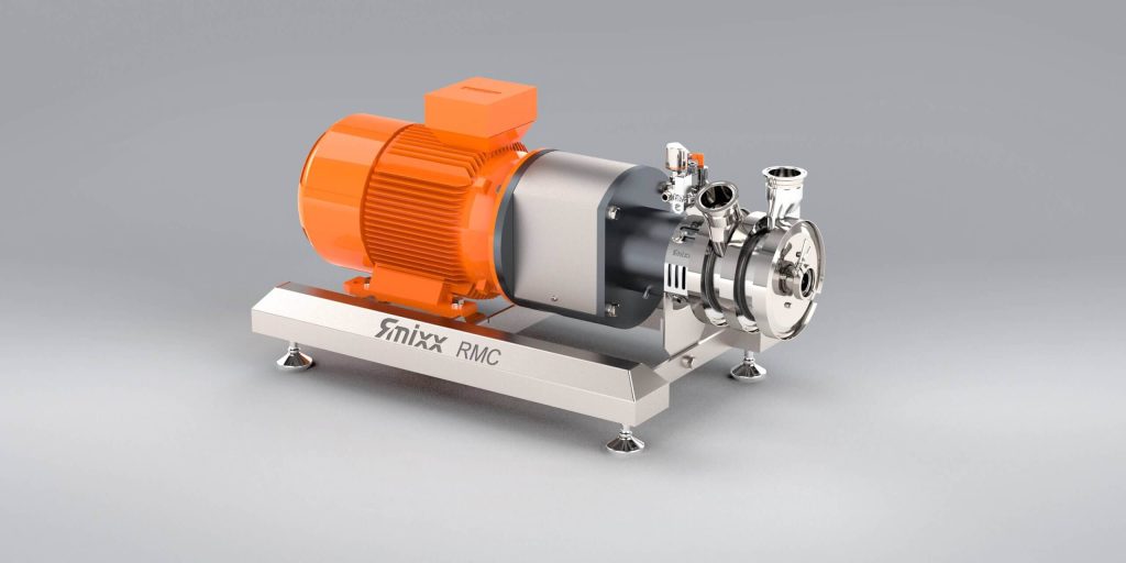 RMC inline powder dissolving machineDraws in powders without dust, dissolves them and disperses them in a single pass. No lumps, no tipping losses.Discover the RMC›
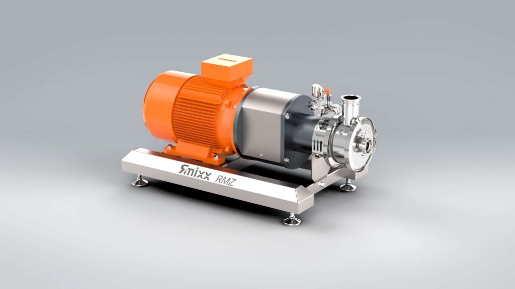 RMZ inline dispersing machineDisperses directly in the pipeline or via recirculation. Produces emulsions and suspensions quickly and reproducibly.Discover the RMZ›
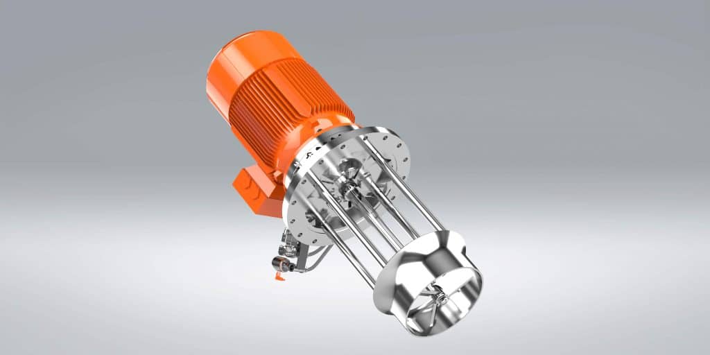 RMY jet stream mixerMixes homogeneously at a range of viscosities, without air entrainment. Available as top entry and side entry.Discover the RMY›
A trial with the actual product is advisable when wear behaviour, wettability or particle hardness cannot be predicted reliably in advance. RS Contracting can conduct such trials in Coevorden or on site, at laboratory, pilot or production scale, depending on the question.
Trend monitoring prevents wear from becoming apparent only upon rejection
Effective maintenance links inspections to product and machine behaviour rather than solely to elapsed calendar time. The relevant inspection frequency differs according to the product, material, operating load, cleaning regime and machine version; a universal interval would therefore create a false sense of certainty.
Record the same data for each inspection: product or recipe, observed process time, quality result, noise or vibration, photographs from fixed angles, location of damage and measures taken. This reveals whether wear is progressing uniformly, accelerates after a recipe change or repeatedly returns in the same location.
When does the deviation occur: immediately after assembly, only with one abrasive recipe or specifically after CIP? An immediate deviation is more likely to indicate assembly, alignment or a damaged component; product-specific wear is more likely to indicate abrasion or chemical compatibility; damage after cleaning necessitates a check of the cleaning chemistry, final rinsing and shutdown conditions.
Preferably schedule an inspection before the available process margin has been used up. A maintenance contract for process machines can help to record inspections, findings and preventive work systematically, without making product-specific assessment unnecessary.
Frequently asked questions about rotor-stator wear
What does normal wear on a rotor and stator look like?
Normal wear is generally gradual and relatively evenly distributed across the loaded working surfaces. Light polishing does not necessarily restrict functionality immediately. Rounded edges, a changed gap, deformed openings or an increasing process time are more important. You should therefore compare the components with reference photographs, dimensions and a previously validated product result.
Can I continue using a worn rotor or stator?
This is possible only if the component is structurally intact, remains within the specified tolerances and the process result remains reproducible. Continuing production is not justified if there are contact marks, cracks, loose parts, metal particles or sudden vibrations. Have the cause assessed before restarting the machine; visual smoothness alone is not a sufficient release criterion.
Why does a new rotor or stator sometimes wear quickly?
Accelerated wear after replacement often indicates a cause outside the new component, such as incorrect assembly, alignment problems, damaged bearings, foreign objects, insufficient product supply or an unsuitable material-product combination. Also check whether a new component has been installed opposite an unevenly worn mating component. Replace it again only after the wear pattern has been explained.
Can a poorer dispersing result also have another cause?
Yes. A higher viscosity, a different raw material, insufficient wetting, air entrainment, a changed temperature, a restricted recirculation path or an incorrect valve position can have the same effect. You should therefore first compare the process conditions and quality data with a good run. Only when these are equivalent does wear of the rotor-stator geometry become a more likely explanation.