Dead zones in a mixing tank are areas where the product is insufficiently renewed, causing the composition, temperature or particle concentration to differ locally from the rest of the tank contents. You do not prevent them simply by increasing the speed or power, but by matching the entire flow loop to the tank geometry, fill level, viscosity and mixing objective. The crucial distinction is that visible movement around the mixer does not yet prove that the product is actually circulating along the wall, bottom and liquid surface.
A dead zone is an area of the tank with a residence time that is much longer than in the main flow, resulting in insufficient mass, heat or momentum transfer. The product does not have to be completely stationary there. A slowly rotating layer may already be dead from a process perspective if powder hydrates, a reaction continues or solids settle before this layer passes through the active mixing zone again.
How dead zones arise in a mixing tank
Dead zones arise when the mixer generates local velocity but causes insufficient bulk velocity throughout the tank. There may be considerable turbulence around a rotor, impeller or mixing element, while hardly any product is exchanged in corners, at the top of the tank or behind internal components. Local shear and complete tank circulation are therefore separate design tasks.
A common assumption is that a stronger vortex or a faster-moving centre of the tank equates to better mixing. A deep vortex may instead show that the liquid is rotating predominantly horizontally and is not being displaced sufficiently in the axial direction. This also increases the risk of air entrainment, foaming and oxidation without improving renewal in hard-to-reach areas.
Tank geometry interrupts the flow loop
Flat bottoms, sharp transitions and an unfavourable ratio between diameter and liquid height can create recirculation areas. An outlet, manway, heating coil, level sensor or CIP component can also create a sheltered area. The product then flows around the obstacle, while an area with little momentum exchange remains directly behind it.
A centrally positioned agitator in a cylindrical tank may primarily generate tangential flow. The product then rotates horizontally as a mass but moves only to a limited extent from top to bottom. Baffles can interrupt rotation and support axial circulation, but they are not automatically the best solution: they add surfaces, welds and potential cleaning shadows.
Viscosity changes during the batch
A mixer must be assessed at the most unfavourable rheology of the process, not only at the initial viscosity. Hydrating gums, polymers, pigment loading or cooling can greatly increase the viscosity during the batch. As a result, the flow can shift from turbulent to predominantly laminar, after which the active mixing zone around the mixing element contracts.
Do you know at what point in your recipe the viscosity peaks? If the installation is assessed only with the low-viscosity starting product, dead zones may arise specifically during powder addition, hydration or cooling. With thixotropic/shear thinning products, the local apparent viscosity near the mixer is also lower than at the wall because the structure is broken down much more strongly there. More background on this relationship is provided in viscosity in mixing processes.
A variable fill level shifts the problem
The position of a dead zone changes with the liquid level. At a low fill level, a mixing element may draw in air or may not be sufficiently submerged; at a high fill level, the circulation loop may not reach the upper section of the tank. Geometry that provides good mixing at the nominal fill level may therefore not function properly during start-up, dosing or emptying.
Does your fill level vary significantly during a single batch? If so, the assessment must cover multiple process phases. An adjustable mixer stand, a different installation position, a side-entry configuration or multiple functional mixing zones may be more suitable than a single mixing element at the bottom of the tank.
“If a viscous product comes to a standstill at the tank wall, rotating faster does not help. You then only create a “deeper hollow ” a vortex in the centre, while the outer layer remains “dead ” from a process perspective.”
Bart Brouwer
Sales Manager
At production scale, this problem often becomes visible only when the batch time increases or samples contradict one another. A small-scale test usually has a different ratio between wall area, liquid height and mixing element. Equal rotational speeds or a similar-looking vortex therefore do not provide reliable scale-up.
The location of the deviation indicates the cause
The location where quality or contamination differs provides an initial indication of the missing flow mechanism. The table links common observations to a probable cause and to the check that provides the clearest distinction.
| Observation | Probable cause | Targeted check |
|---|---|---|
| Sediment or unprocessed powder on the bottom | Insufficient downward axial flow or insufficient bottom velocity | Check the flow path to the bottom and outlet during the most demanding process phase |
| Product layer on the wall or in corners | The main flow short-circuits around the mixing element | Compare wall samples with samples from the centre of the tank |
| Temperature difference between sections of the tank | Insufficient bulk circulation along heat-transfer surfaces | Measure simultaneously at multiple heights and radial positions |
| Foam at the top but a poorly mixed bottom | Excessive surface rotation and air entrainment, insufficient axial circulation | Observe both the liquid surface and bottom behaviour at the same fill level |
| Residual product behind fittings after CIP | Flow shadow or insufficient cleaning impact | Carry out targeted cleaning validation of the shielded area |
Does your product actually flow along the wall, or is it mainly the centre that rotates? A rotating surface does not answer that question. The relevant criterion is whether every product fraction returns within the required process time to the zone where mixing, heat transfer or dispersion takes place.
Identifying dead zones without relying on visual inspection
You identify dead zones by measuring both spatial and time-dependent differences. A single sample from a favourably positioned sampling valve can make a batch appear homogeneous, while product at the bottom or behind a fitting remains different. The measurement method must therefore correspond to the failure mechanism you suspect.
-
Record all process phases. Note the dosing sequence, fill height, temperature development, position of the mixing element and the point at which the rheology changes.
-
Select an appropriate tracer or quality parameter. Conductivity, temperature, colour, density, concentration or a product-specific analysis method can reveal local exchange.
-
Measure at multiple positions. Take samples or readings at the bottom, centre, wall and upper product layer, insofar as this can be done safely and representatively.
-
Track the response over time. An ultimately equal value says little about the speed at which a hard-to-reach zone is renewed.
-
Repeat under critical operating conditions. Do not test only with water, but where possible assess the actual product or a representative medium at relevant fill levels.
-
Check the effect of the adjustment. Confirm that the variation between locations decreases without causing new problems such as air entrainment, heating or product damage.
The sampling position is decisive here. Where do you currently take your release sample: from a well-flowing recirculation line, from the centre of the tank or at the outlet? A representative assessment combines locations because it is precisely the comparison between the main flow and the suspected sheltered area that reveals a dead zone.
Computational fluid dynamics can provide advance insight into flow patterns, velocity gradients and potential recirculation areas. However, a CFD model remains dependent on correctly entered rheological data, boundary conditions and geometry. It does not replace a product test when non-Newtonian properties, settling, gas entrainment or changing viscosity determine the process.
Eliminating dead zones starts with the required mixing result
The correct intervention depends on what must be achieved in the tank: bulk homogeneity, heat transfer, mixing, suspending, dissolving, emulsifying or dispersing. A solution that improves tank circulation does not automatically provide sufficient shear stress to break down agglomerates. Conversely, a rotor-stator can disperse intensively at a local level while the supply from the rest of the tank is insufficient.
First restore the complete circulation loop
The first design step is to ensure that the product flows from the mixing element to the distant areas of the tank and then returns. This may require a different axial flow direction, adjusted positioning, a different mixing element or a jet stream that transfers momentum over a greater distance. At high viscosity, the geometry must prevent only a narrow product column around the shaft from moving.
Baffles are useful when unwanted tangential rotation dominates and the hygienic requirements permit them. They are less suitable when adhesion, fibre accumulation or cleanability are critical risks. In those situations, eccentric positioning, an adjusted inflow direction or a different mixing technique may provide a better flow loop with fewer internal obstacles.
Separate tank mixing and high-shear processing when necessary
One machine does not have to perform all process functions in the same location. A tank mixer can keep the bulk homogeneous, while an inline rotor-stator draws product from the tank through recirculation and disperses or emulsifies it in a controlled manner. The return position must then prevent treated product from being drawn in again immediately while other parts of the tank are bypassed, a so-called short-circuit flow.
The choice between batch and inline processing also depends on residence time, product feed and the desired particle size distribution. The differences are explained in inline and batch dispersing. High shear is not the correct solution when only bulk circulation is lacking or when the product is sensitive to structural damage, unwanted heating or air entrainment.
Match the technology to the product and process phase
At varying viscosities, a targeted jet stream can support tank circulation, while inline recirculation may be suitable for controlled powder induction or dispersion. The combination must be selected on the basis of rheology, density difference, settling behaviour, wettability, tank geometry and the course of the batch. Without these data, it is not possible to determine reliably which configuration will actually eliminate the dead zones.
For processes combining bulk circulation, low-dust powder addition and reproducible dispersion, a jet stream mixer for tank circulation, an inline powder dissolving machine and an inline dispersing machine are separate or combined building blocks. The appropriate combination must be determined by the function that is missing in each process phase.
The right machine for your process
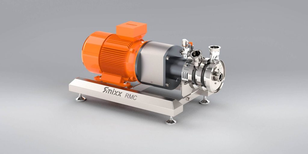 RMC Inline powder dissolving machineDraws in powders without dust, dissolves them and disperses them in a single pass. No lumps, no pouring losses.Discover the RMC›
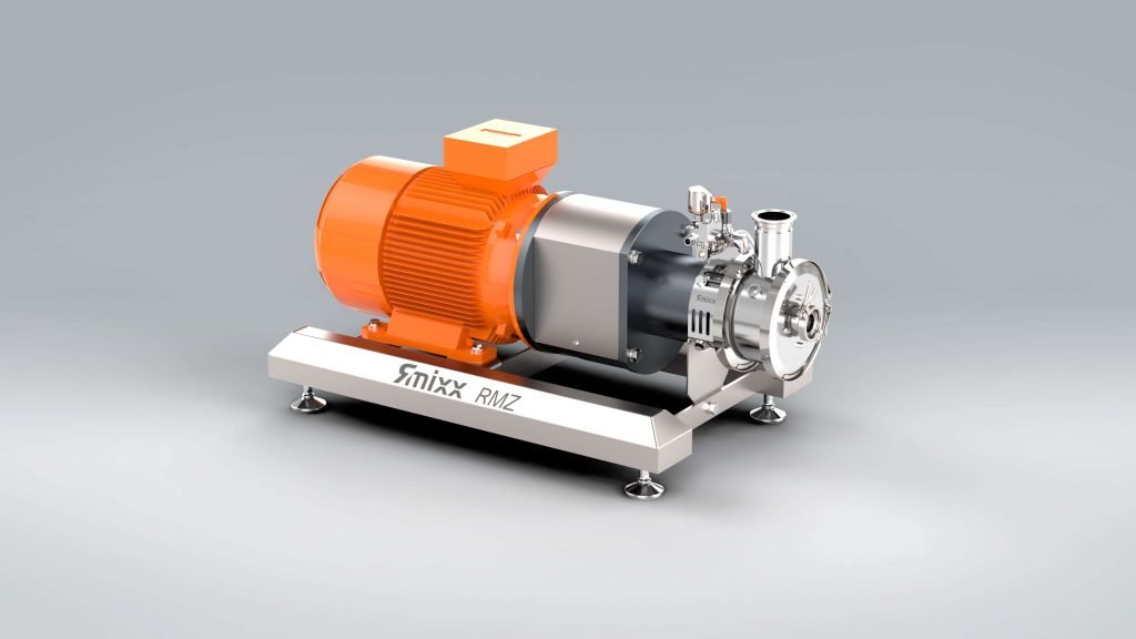 RMZ Inline dispersing machineDisperses directly in the line or through recirculation. Produces emulsions and suspensions quickly and reproducibly.Discover the RMZ›
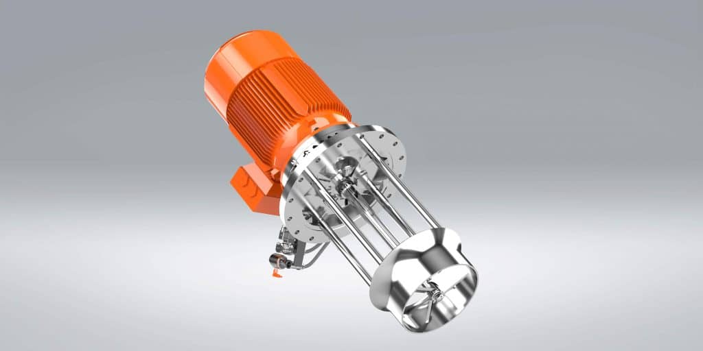 RMY Jet stream mixerProvides homogeneous mixing at varying viscosities without air entrainment. Available as top entry and side entry.Discover the RMY›
Adding more equipment is not always the best correction. Sometimes the cause is an incorrectly opened valve, a contaminated rotor, a reversed direction of rotation, a changed dosing sequence or wear that prevents the original flow from being achieved. The existing installation should therefore be checked before any major modification is undertaken.
Cleanability turns a flow problem into a quality risk
A product-related dead zone can also be a hygienic dead zone, but the two concepts are not identical. During production, the issue is insufficient product renewal; during CIP, it is insufficient cleaning agent, mechanical impact, temperature or contact with the contaminated surface. An area may have acceptable flow during mixing yet remain shielded behind an internal component during cleaning.
In food, cosmetics and pharmaceuticals, residual product can cause cross-contamination, microbiological growth or deviations in a subsequent batch. Hygienic design therefore requires drainable surfaces, suitable connections, as few product-trapping details as possible and demonstrable cleanability. EHEDG, 3-A Sanitary Standards and GMP provide relevant design frameworks; the applicable requirements depend on the product, market and validation strategy.
CIP is not a remedy for a poorly designed flow shadow. A longer cycle does not automatically correct a surface that is not reached or a cavity that does not drain. Practical points for construction and validation are provided in hygienic design and cleaning.
From process deviation to a substantiated correction
A lasting correction follows from a causal chain, not from a single isolated observation. You should therefore link the quality deviation to the process phase, position in the tank and product property. This prevents you from specifying a more powerful mixer when the actual cause is an unfavourable return line or changed viscosity.
-
A homogeneous sample from the recirculation line does not prove that the entire tank is homogeneous.
-
A powerful vortex proves surface rotation, but not sufficient vertical tank circulation.
-
More shear breaks down agglomerates but does not remedy a lack of supply from a remote area of the tank.
-
A water test demonstrates the flow of a viscous or non-Newtonian product only to a limited extent.
-
A design must function at critical fill levels and during the most unfavourable rheological process phase.
For a new installation, a product test is often the most reliable step when rheology, wettability or settling behaviour cannot be predicted sufficiently. RS Contracting can conduct tests in Coevorden or at the customer’s site. This allows the mixing pattern, powder induction, recirculation and product quality to be assessed together before the configuration is finalised.
Frequently asked questions about dead zones in a mixing tank
How do I recognise a dead zone in a mixing tank?
You can recognise a dead zone by persistent differences in concentration, temperature, colour, viscosity or solids content between locations in the tank. Sediment, deposits on the wall and deviations in the first or last product discharge are also indications. Confirm your suspicion with measurements or samples at different heights and distances from the mixer during the critical process phase.
Can I eliminate dead zones by increasing the rotational speed?
A higher rotational speed helps only if it actually restores the missing circulation loop. It may also primarily increase local shear, vortex formation, air entrainment and heating. If the tank geometry, mixing element or installation position restricts the flow, a geometric or process-related adjustment is generally more effective than simply increasing the speed.
Are baffles always necessary in a mixing tank?
Baffles are not always necessary. They can interrupt tangential rotation and improve vertical circulation, but they can also cause adhesion and cleaning shadows. For viscous, fibrous or hygienically critical products, a different mixer position or flow direction may be more suitable. The choice depends on rheology, tank shape and cleaning requirements.
Why does a small-scale test not guarantee performance in the production tank?
During scale-up, the ratios between tank diameter, liquid height, wall area and mixing element change. This changes the circulation length, residence time and relative effect of viscosity. Equal rotational speeds or a similar visual mixing pattern are not valid scale-up criteria. A representative pilot or product test must include the critical product properties and process phases.
When is an inline mixer not a solution for dead zones?
An inline mixer is not a complete solution when the suction and return points short-circuit only a small part of the tank. The machine then repeatedly processes the same product fraction while remote zones are left behind. Inline processing works properly only when tank circulation conveys all product fractions to the recirculation circuit and the return flow is distributed in a targeted manner.